DRSSTC 1
Sat, 09 April 2011. 02:41AM
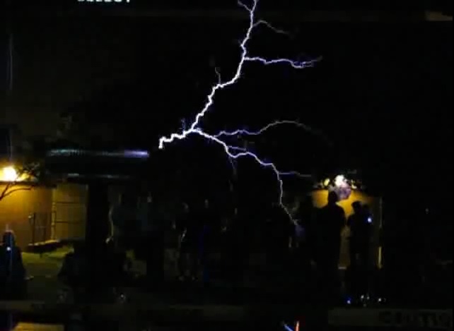
It's hard to imagine, how the beautiful branched lightnings of Singing Dual-Resonant Solid State Tesla Coil can sometimes charm a people.
For the first time I saw a singing Tesla coil about year ago. It was a Youtube video of Steve Ward's DRSSTC2 showed June 9 2007 on DucKon 16 festival in Naperville, Illinois, USA.
I have been completely charmed of the unique sound of DRSSTC. The beautiful sound of lightning bolt.
The more I listened the more I became obsessed of singing Tesla coils and became desired to step into this terra incognita of making my own one.
I began to learn more about it, read the pages, search for a people in my country who already had a deal with it and finally who live in my town. Shortly I found the guys with nicknames "X-Ray" and "Quartz", members of flyback.org.ru - russian clone of 4hv.org.
I met them, join they local crew and start to make a coil.
It took about a year for make things right, make a money, got a parts, learn how to solder, make pcb design, assemble the system, etc. Really, a year ago I didn't know the difference between capacitor and resistor. It was just a parts for me and I was not sure I could take off ground this. I made attempts one by one, got an explosion of IGBTs, done a repair, start again, got an explosion again and again, but I believed that I could do it.
And then, finally, I made my first DRSSTC!
Description:
The coil is a resonance transformer with frequency modulation of current of primary inductor of transformer
The current modulation needs to force a transformer works in resonant mode
The secondary inductor have a resonant frequency, as a combination of 1/2*pi*sqrt(L*C)
So the transformer will work in resonant mode if the primary inductor sinusoidal current will grow up and fall with same frequency
for that could happen, the insulated-gate bipolar transistors of primary transformer circuit should opens and be closed in time
which clocked by the DRSSTC driver board
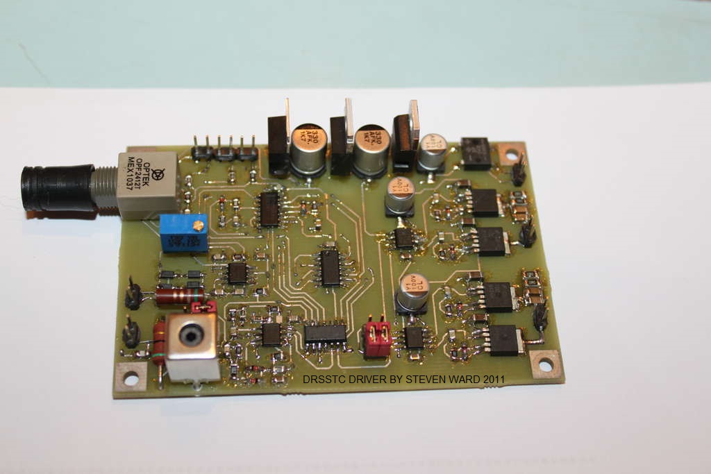
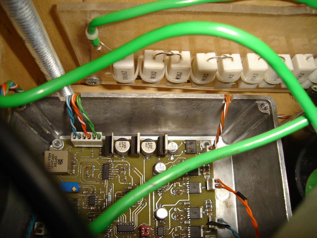
In that coil a used a Steve Ward's driver board from his DRSSTC3 page
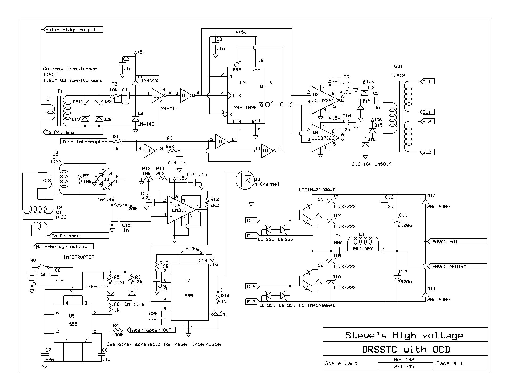
PCB design was made in Sprint Layout software. PCB board was made by photoresistive technology of making PCB.
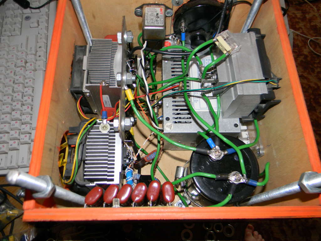
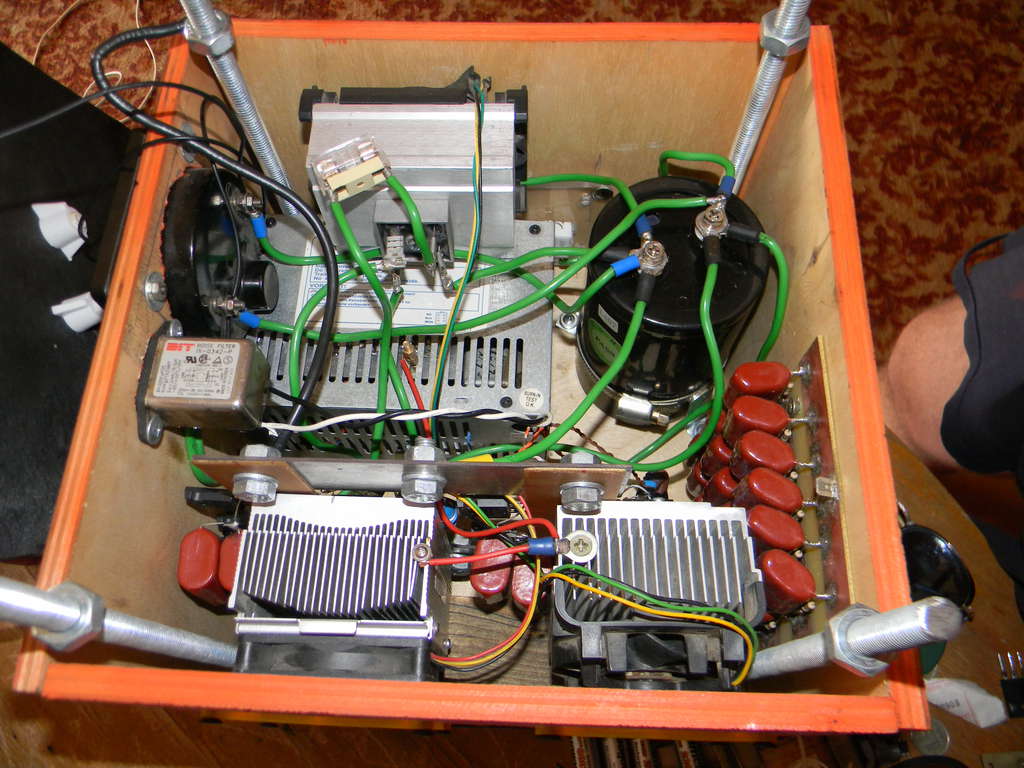
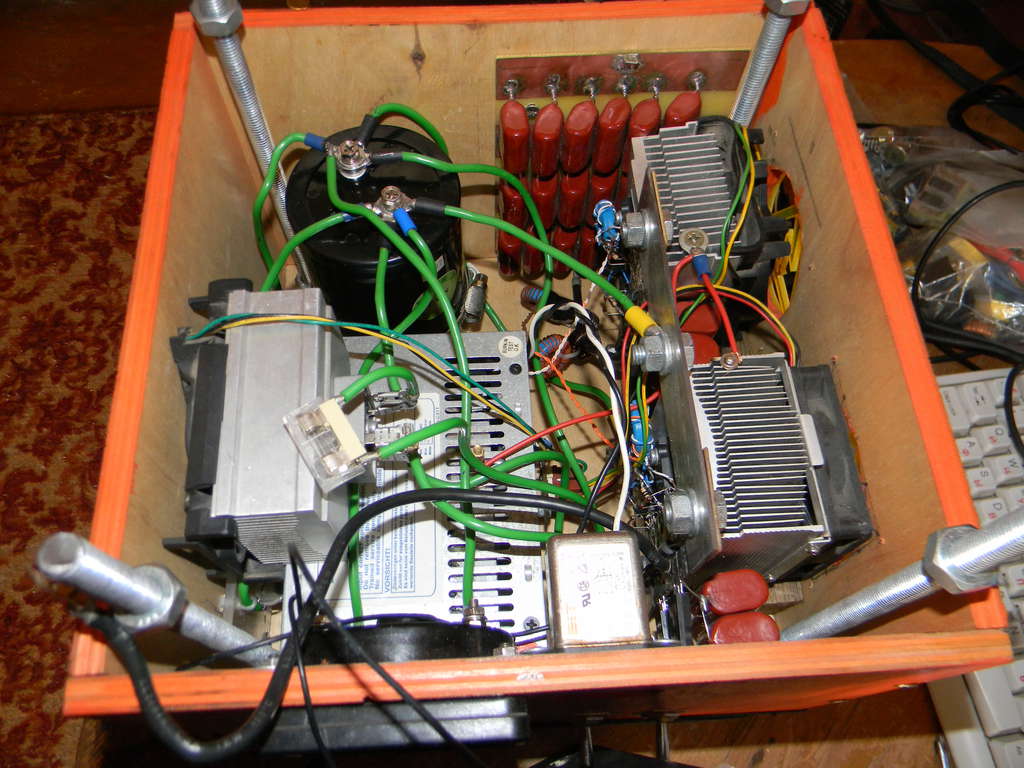
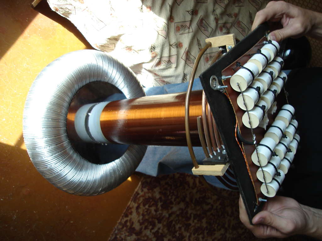
The coil is a two circuits. Primary and Secondary. Secondary circuit consists of a inductor and topload. Primary consists of an inductor, capacitor and swithes block.
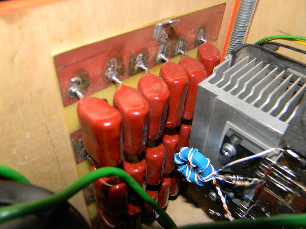
Capacitor often consists of many capacitors in series and parallel. And named MMC - Multi-Mini Capacitors.
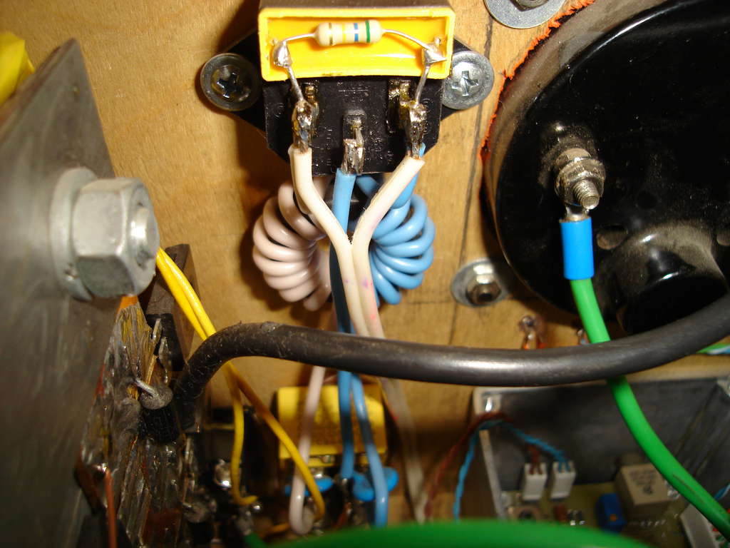
Switching block consists of bridge rectifier, bus electrolytic capacitors, insulated-gate bipolar transistors, transient voltage supressing diodes, snubber capacitors, gate drive transformers, current transformers, driver and interrupter.
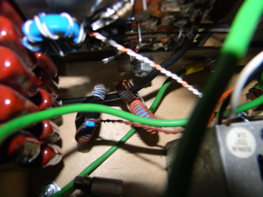
In my coil I used of two GDT in combination of 1:2:2 with core matherial of Epcos N87 with dimensions of 22х13х6mm, wired with help of BSVi's GDT calculator.
I choose a full bridge topology and IRG4PC50UD IGBTs, HFA25PB60 ultrafast diodes, 1.5KE400CA transient voltage supressors, 15v zener diodes to gate-emitter, 10 Ohm resistor + 1N5819 diode to the gate charge-discharge circuit, and 18.8uF film snubber capacitors to the bridge.
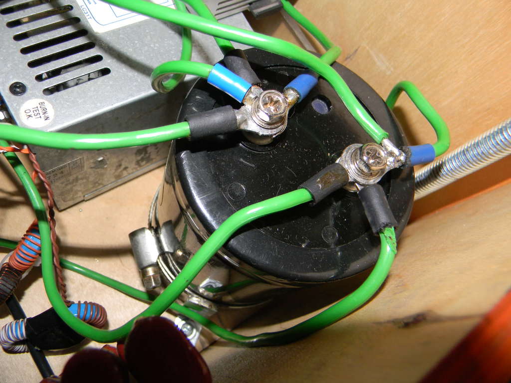
The bus capacitor I used is a CAPXON 4700uF 400V, actually may have high ESR, which is not good, but it cheap and working.
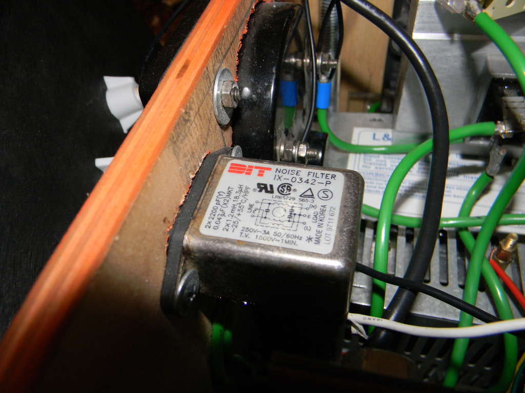
I also used a noise filter to shield the power line of electromagnetic interference.
Charge resistor for bus cap 10 Ohm 10W. After some time, it burned down and was replaced by big green soviet resistor.
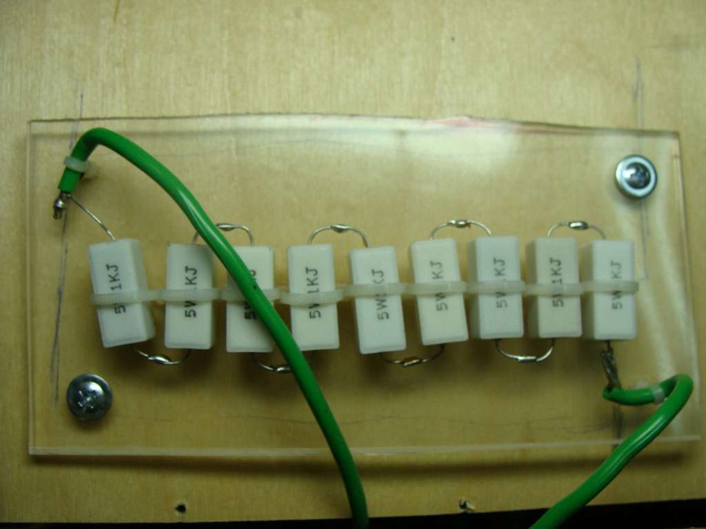
and discharge 9kOhm 45W resistor, for bus cap. It definitely should not be looking like this, but I was young and inexperienced
MMC 250nF-3kV teflone Suntan 3A154K.
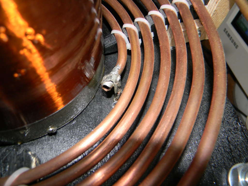
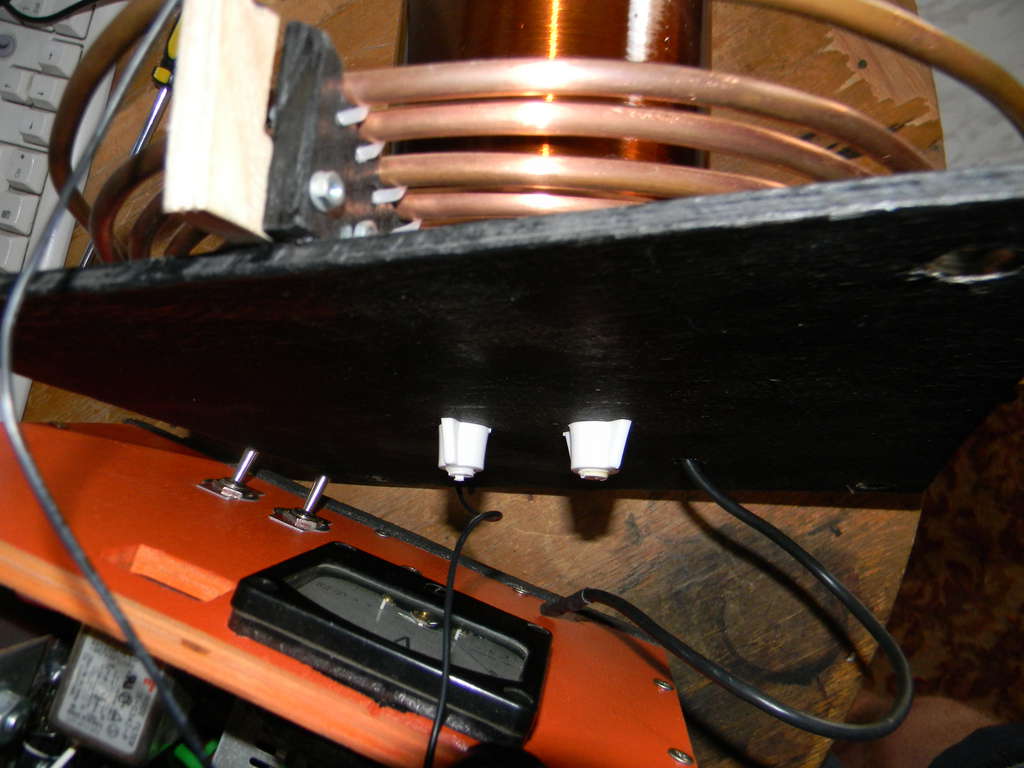
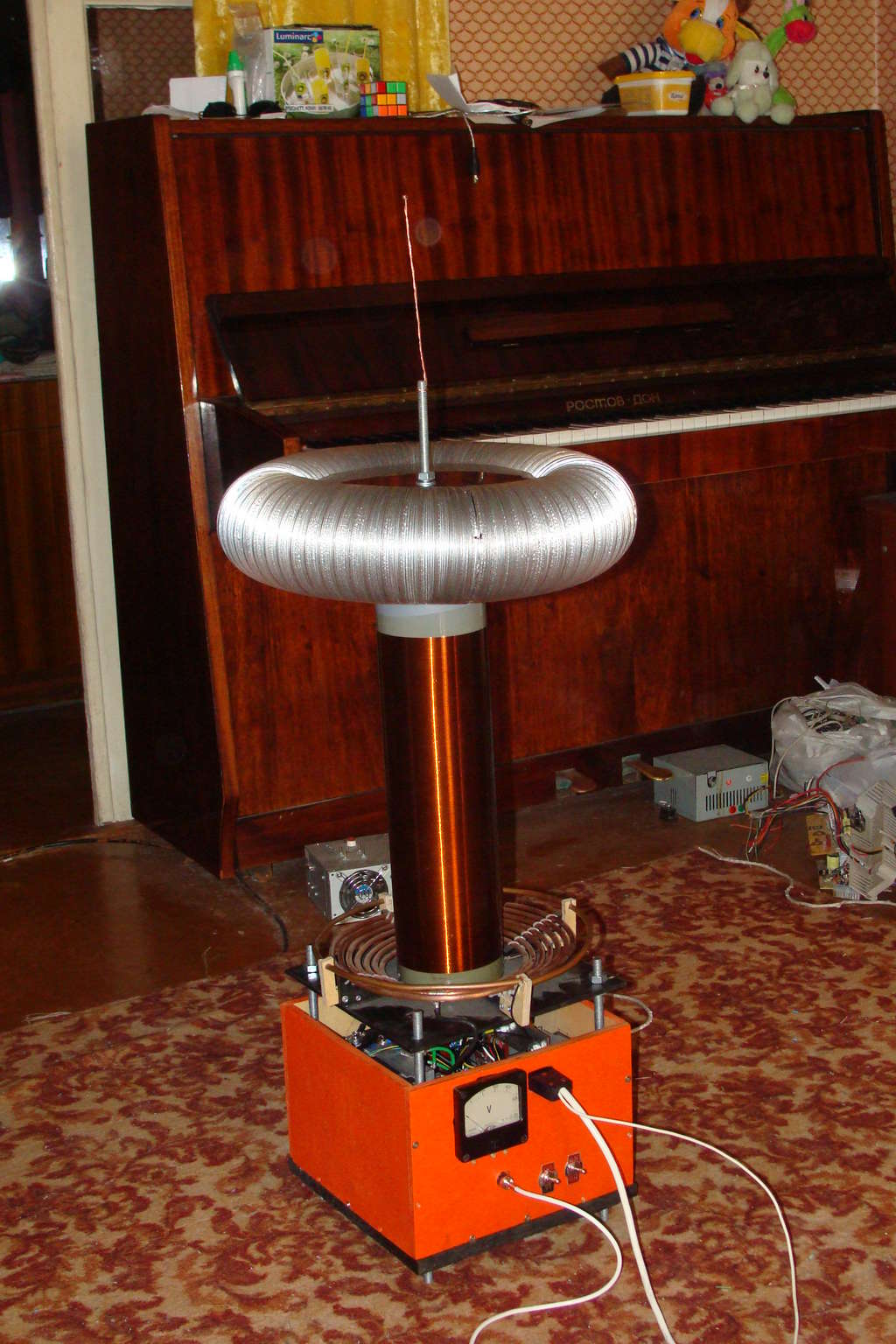
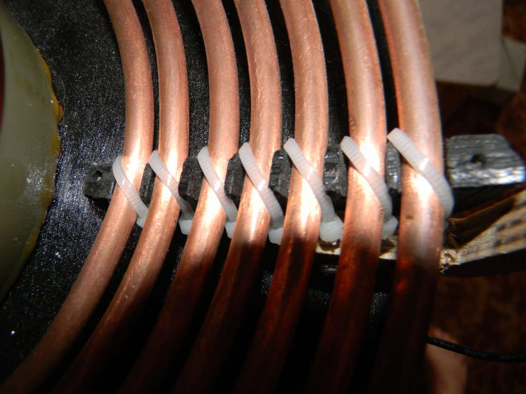
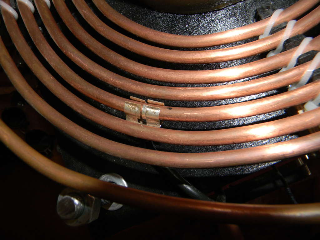
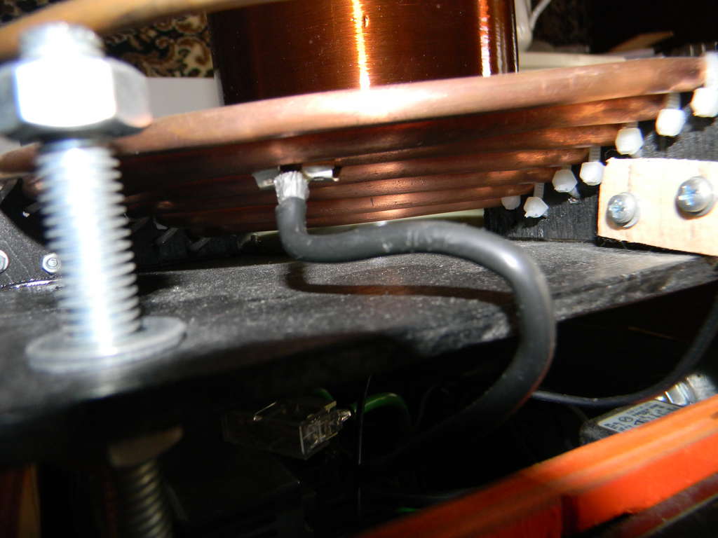
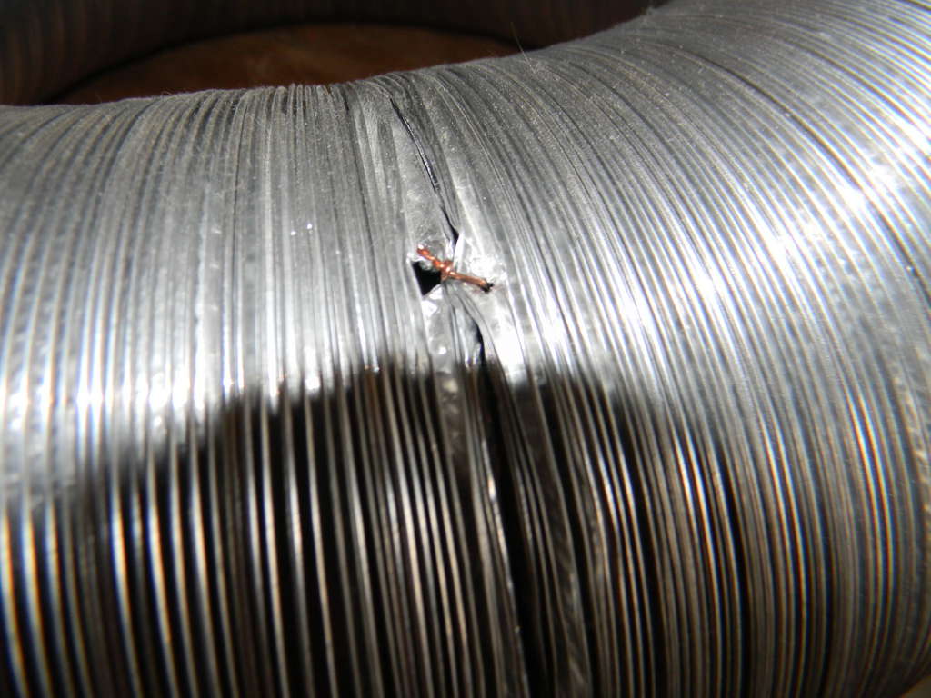
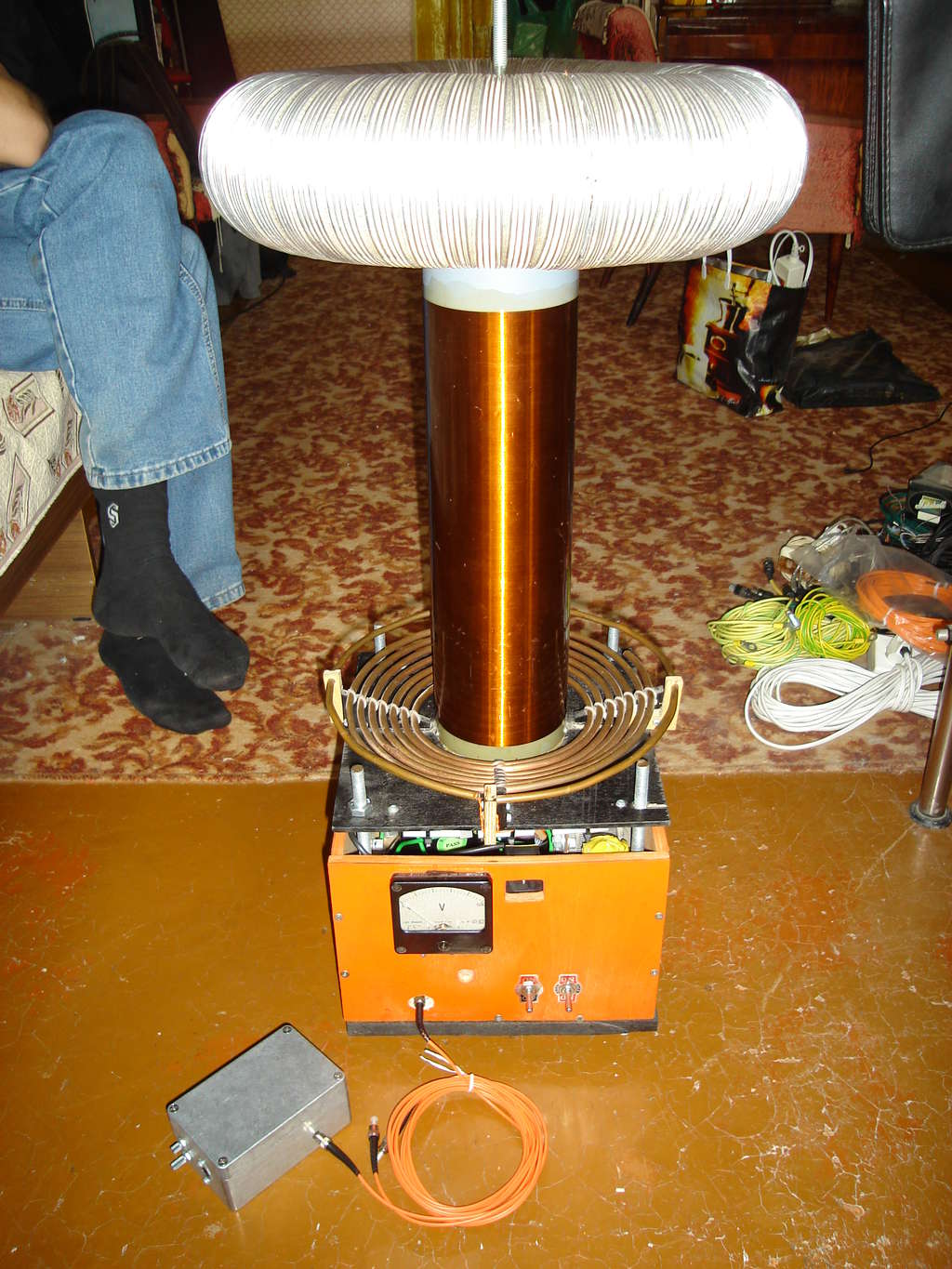
V-looked primary inductor - 6mm hollow copper tube from M1M copper matherial, internal inductor diameter is a 13cm, external diameter 24cm, height 2cm. The last external special ring is a grounded strike-ring for catching spark and avoiding spark to get the inductor.
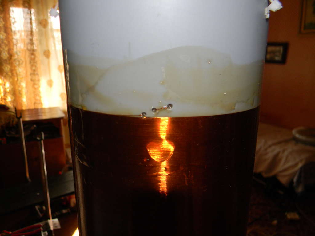
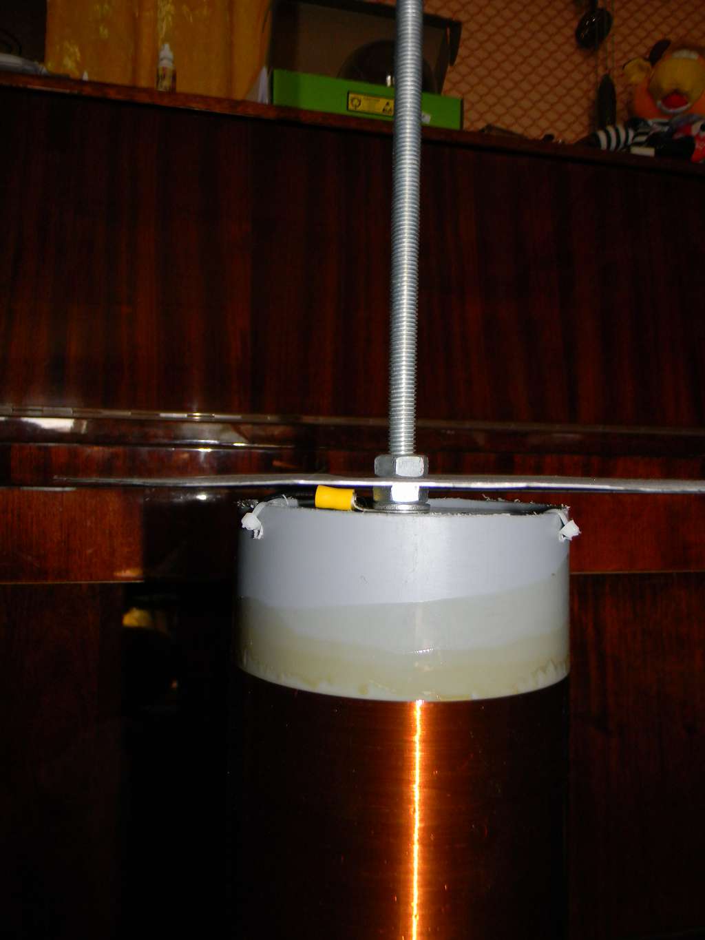
Secondary inductor wired on PVC hollow tube with 11cm diameter. Wired of 0.2mm old soviet epox copper wire. wire lenght 38,4cm. covered by 3 or 4 layers of Polyurethane with some strange name "yacht's varnish". Secondary pipe is connected with box with PVC screws to avoid induction heating from primary inductor.
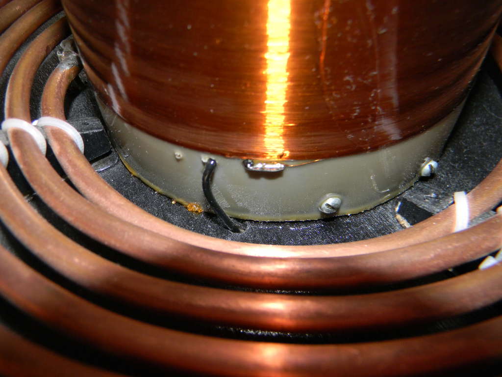


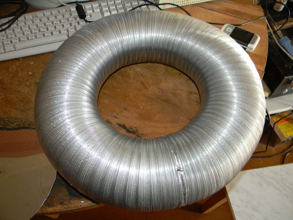
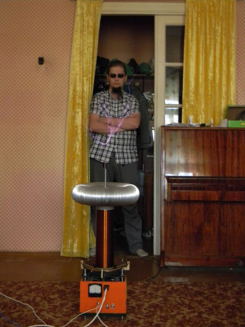
Topload is a bent aluminium airduct with dimensions of 40x10cm. Topload acting like a capacitor for secondary circuit and lowering the resonant frequency. With that inductor and topload mine f(sec)=105kHz.
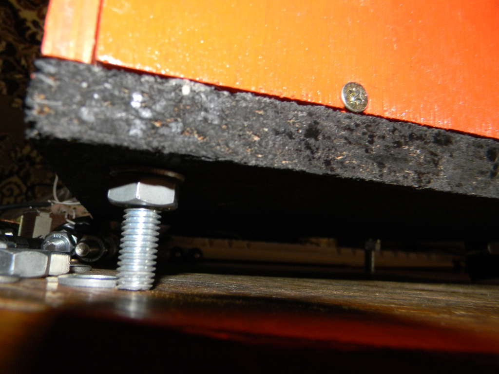
Orange plywood varnished box. Love the orange color.
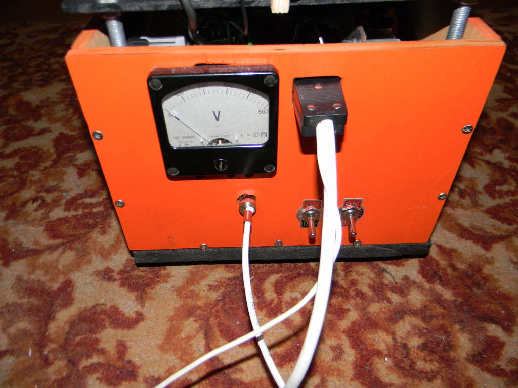
To start a coil first I switch-on the left switch, which sent a current through the charge resistor, then the second switch put charge resistor away from a curcuit when bus cap became full charged.

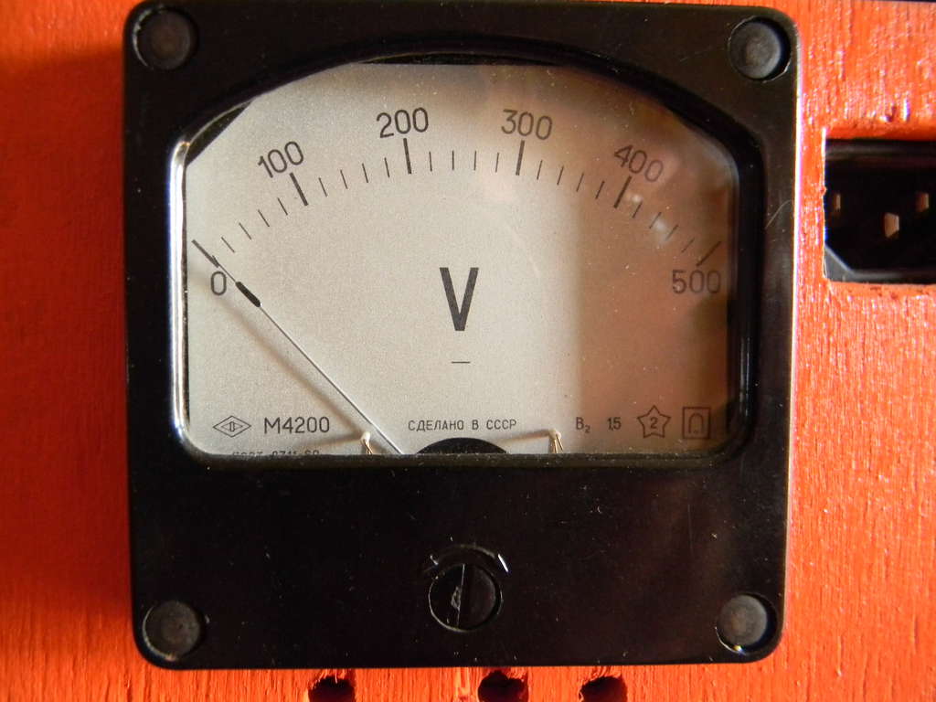
Nice vintage voltmeter help me see the voltage on a bus.
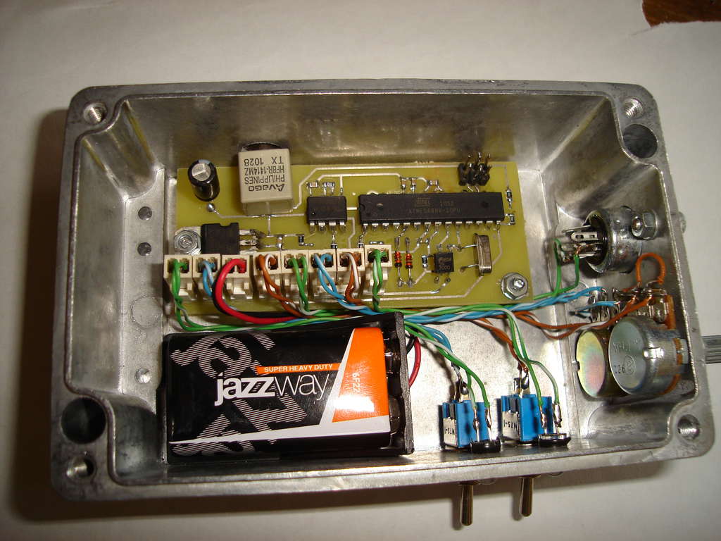
The Interrupter sends a square pulse to the driver to command the driver to start swithcing the IGBTs
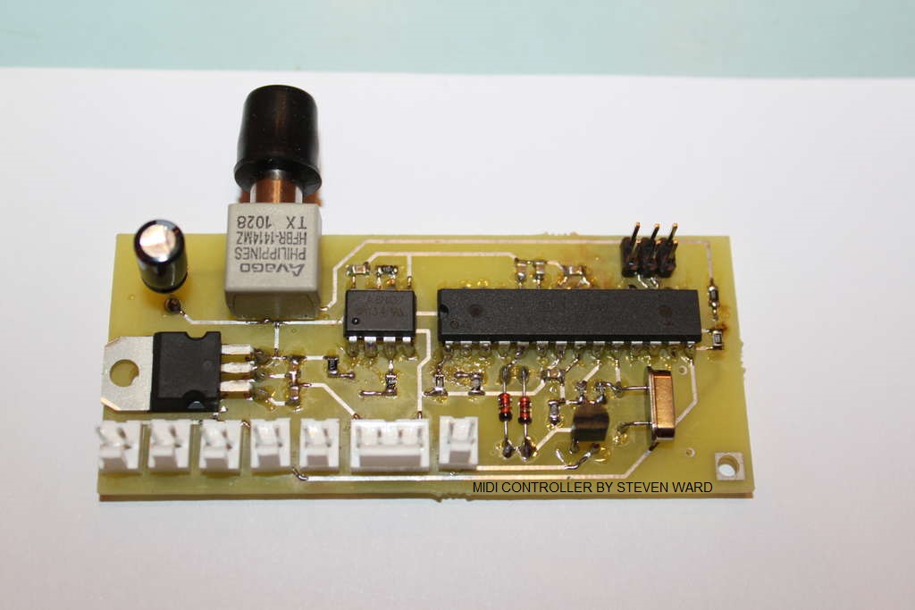
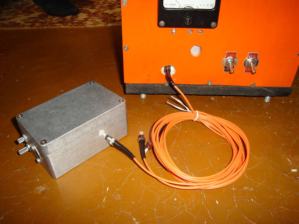
It could be on NE555N or on MCu like a midi controller "i1" by BSVi
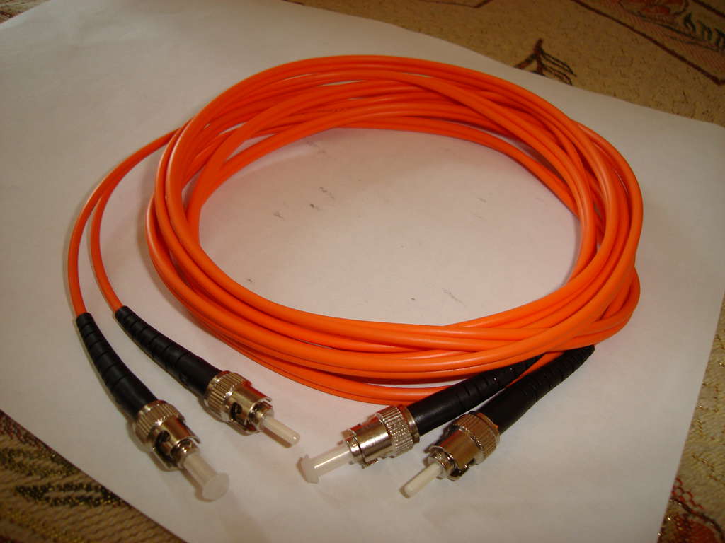
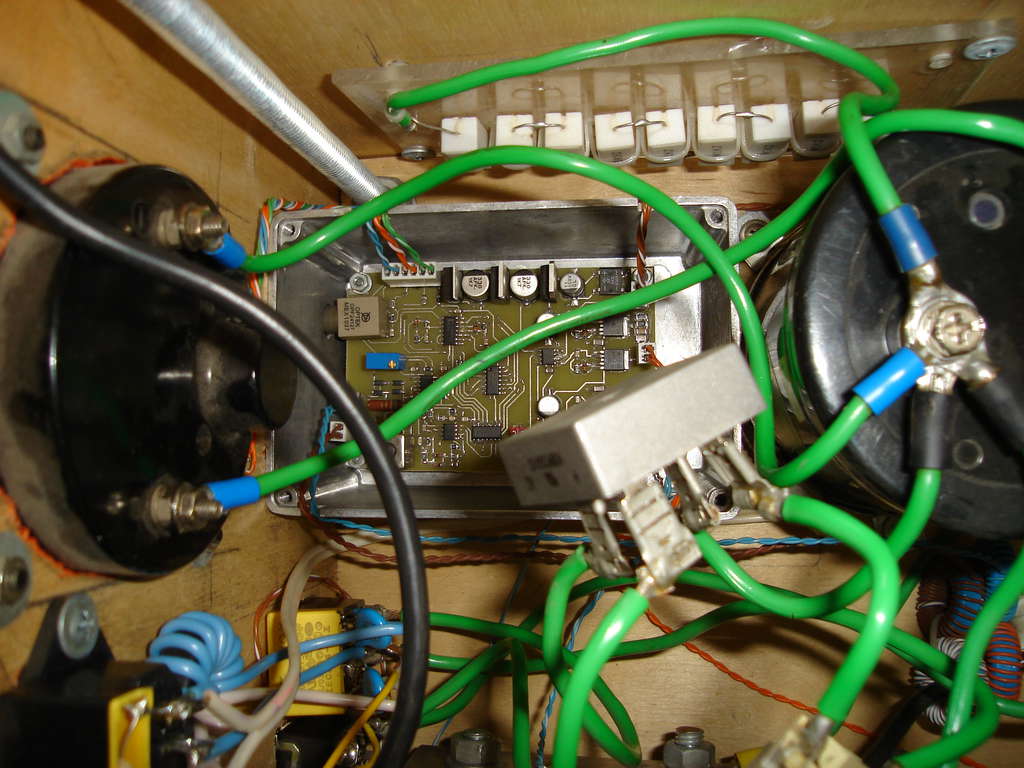
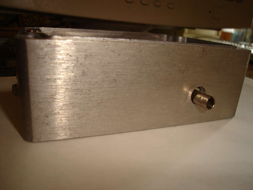
Interrupter and driver have been placed into aluminium boxes from PC's PSU and connected with each other by BNC cable.
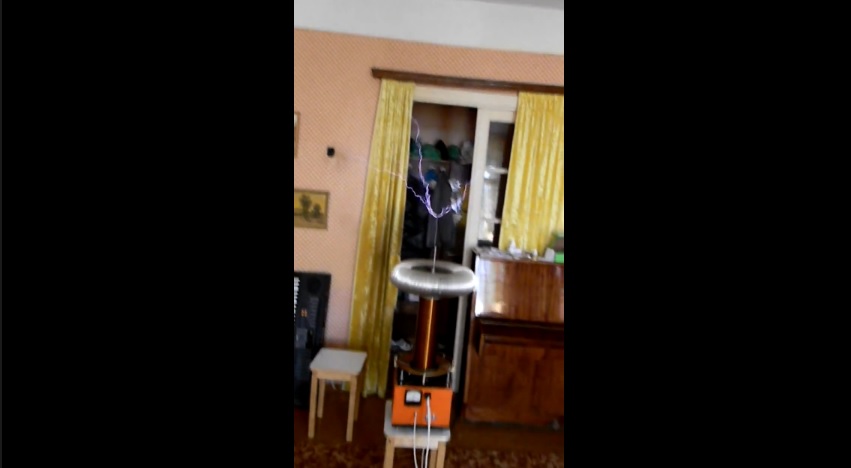
Sparks is about 50cm. Some photos and videos now.

Lightnings
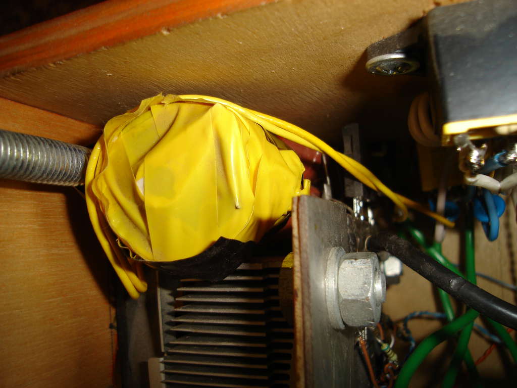
The fuse. If you don't use it, your wires can be damaged
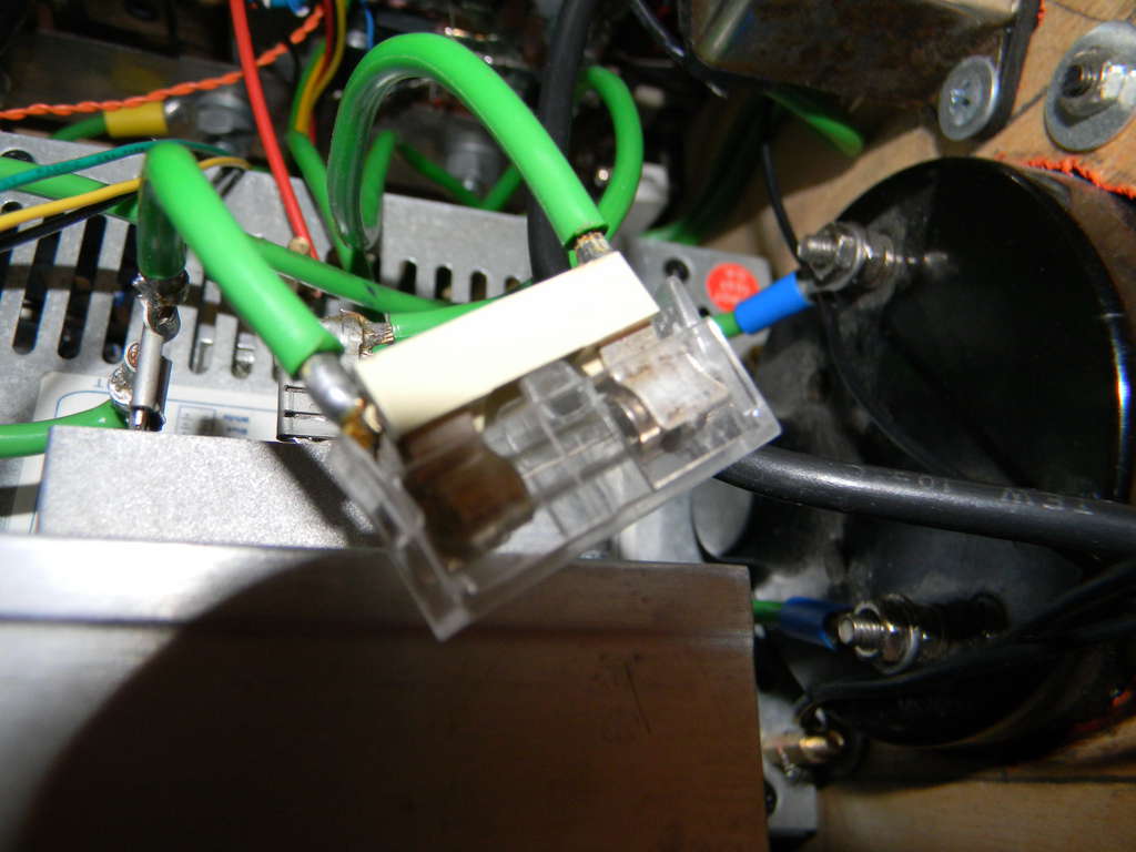
Film caps are here, 4.7х4=18.8uF total.
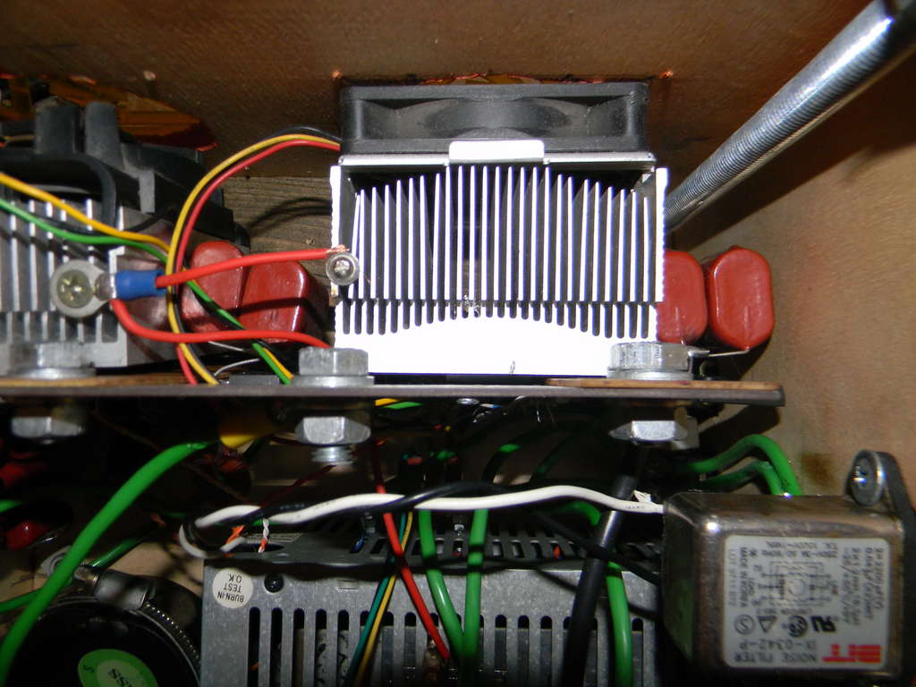
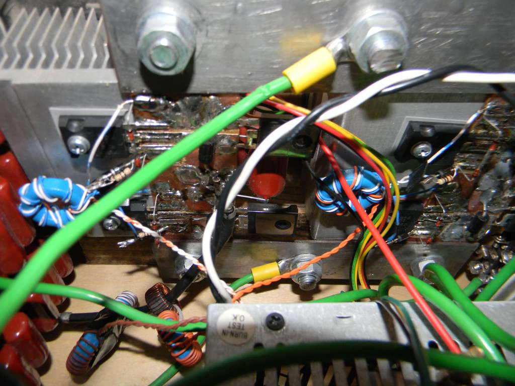
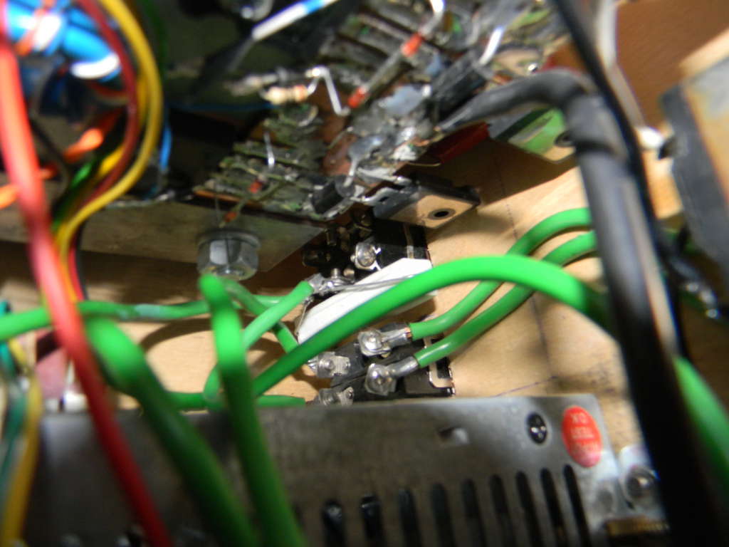
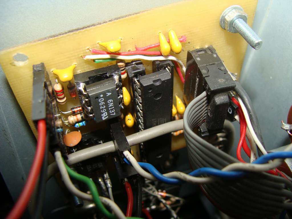
Part of swithcing system.

Current transformers for driver feedback and over current detect systems.
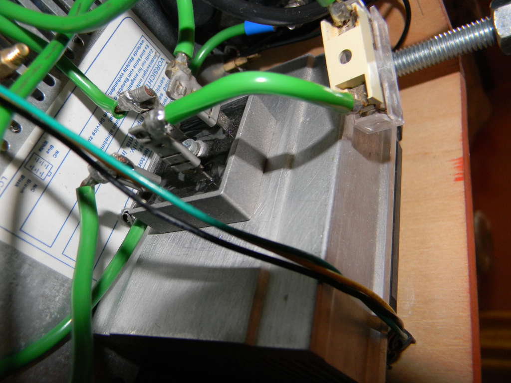
Bridge rectifier.
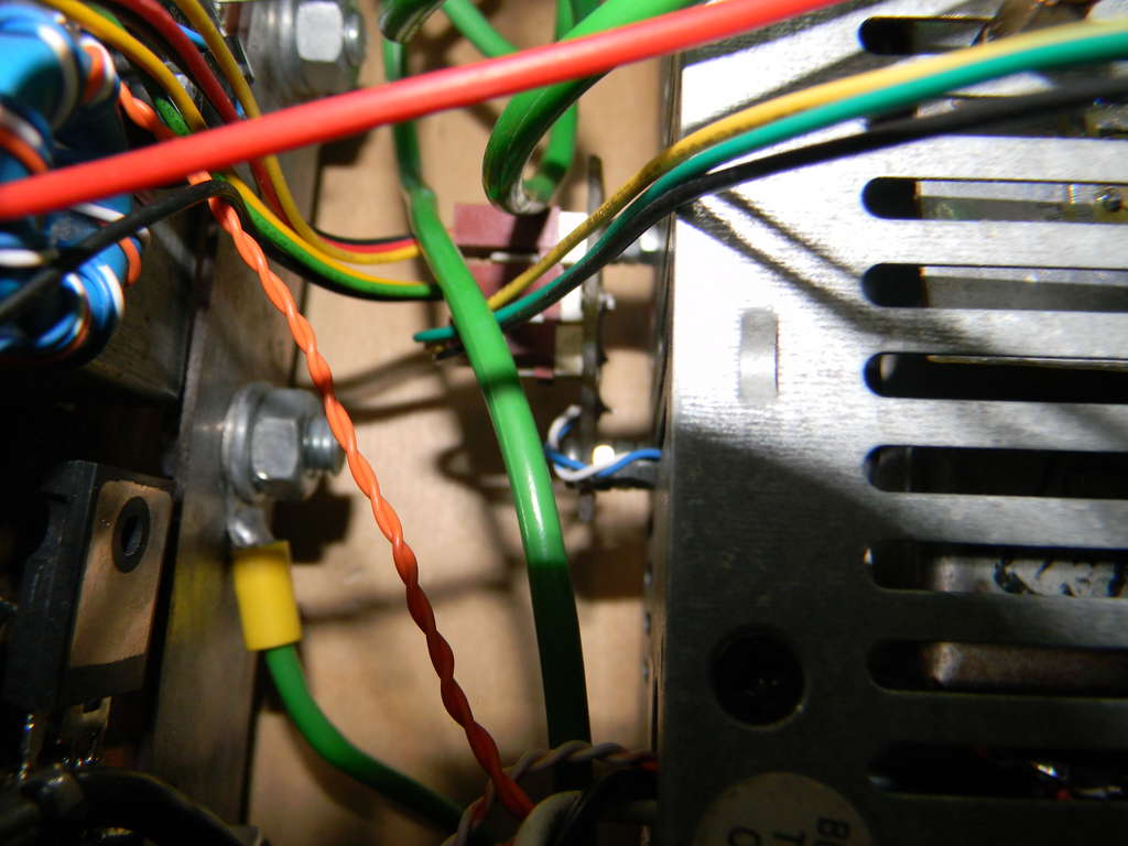
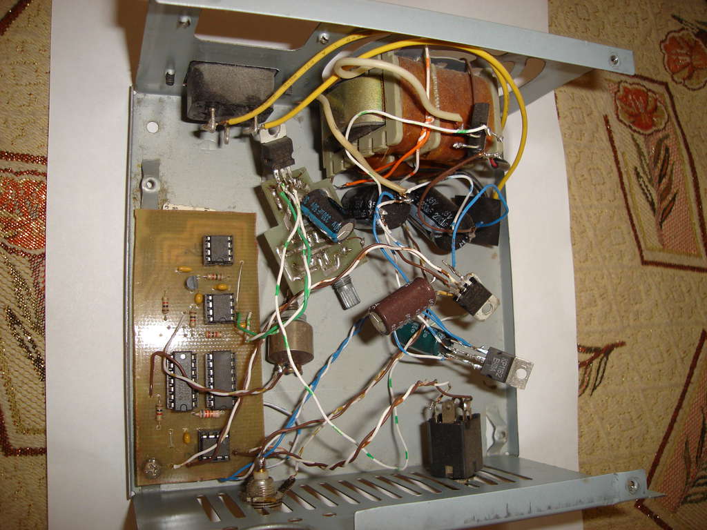
Guts.

Primary fits on box by nylon tie.
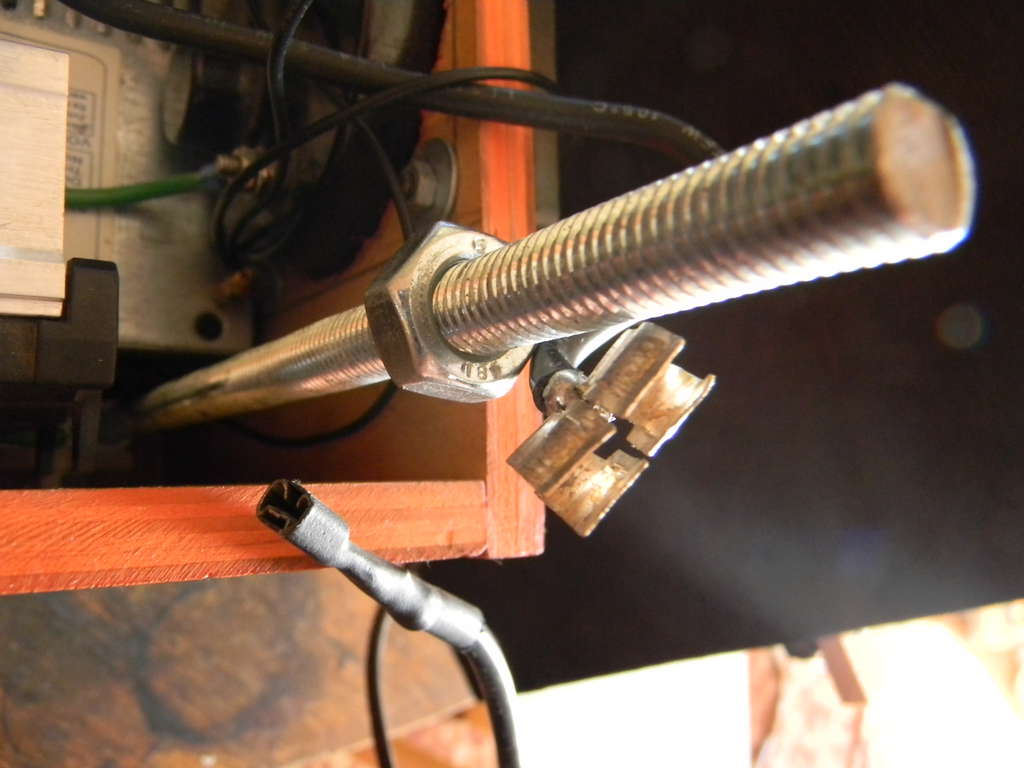
To connect the sliding contact I used contacts from the mount-plate fuse box, after choose the size of contacts of the fuse according to primary diameter.
Wire for sliding contact.
Grounded strike-ring.
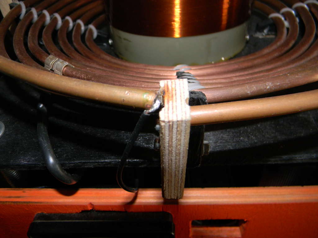
secondary inductor with toroid connector.
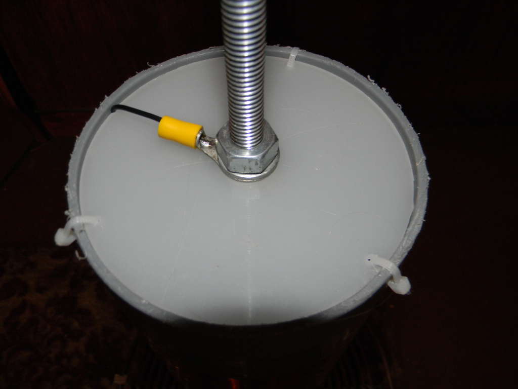
toroid connector.
another one
Yep, this is it. Dead IGBTs. Interrupter BNC wire had a bad ground connection.

Oh, it's me.
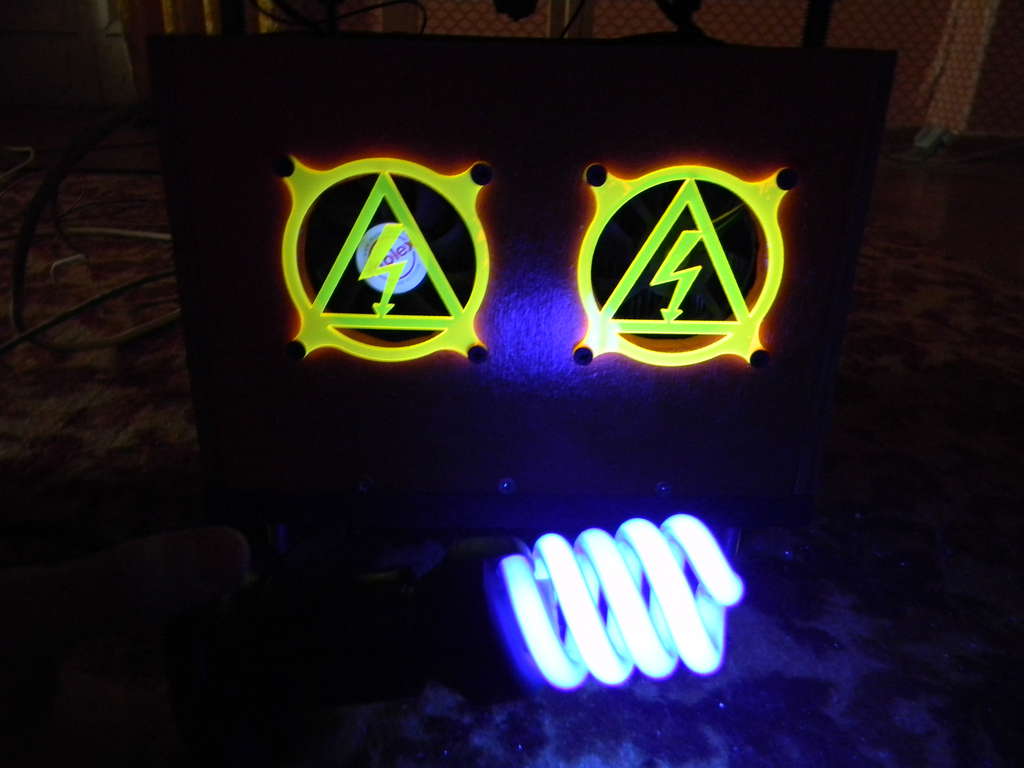
flourescent grills under ultraviolet light :3
dedicated fan board.
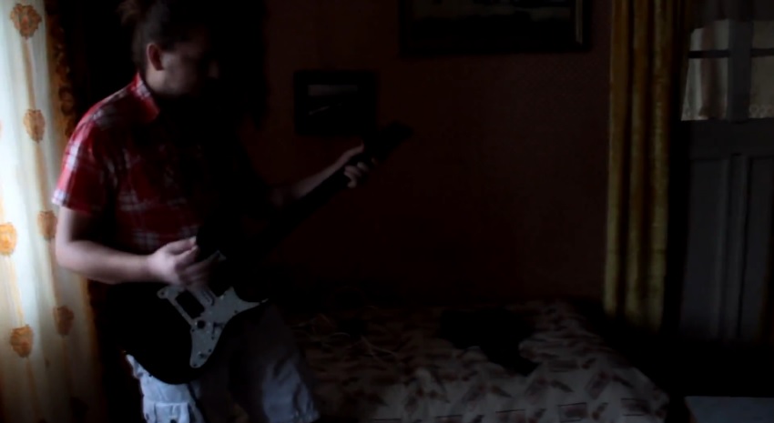
UPD: Hi guys, some updates.. Audio interrupter looks like done. My DR are the guitar amp! ^,..,^
UPD: Updates on driver. Thanks Steve Ward for Universal Driver 2.0revB rev march 26, 2011.
Also, a new interrupter. This is duophonic midi controller by Steve Ward, from early 2008. On the high BPS it come to reduce pulse width, and now, highest notes become alive on DR. Thanks again, Steve.
UPD: It was a long time I shared some updates.
New CDE MMC, driver box, st-st fiber optics, new interrupter in box. Some photo.
audio interrupter's first breadboard-like design
MMC
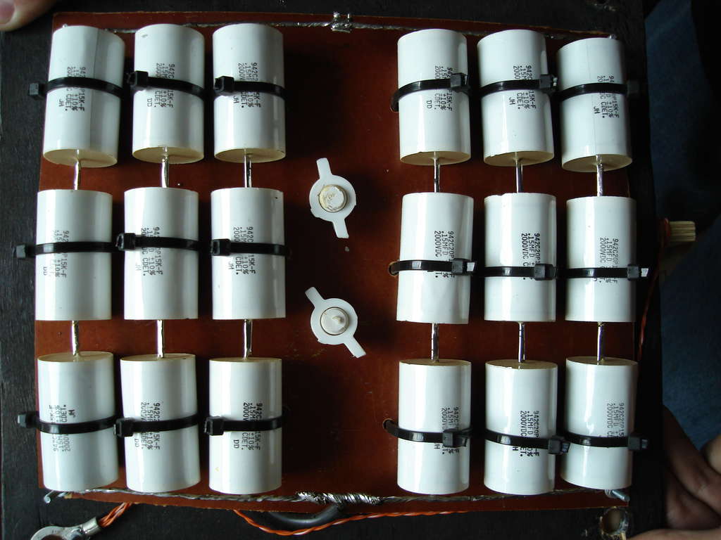
MMC again
New Noise filter.
New huge soviet charge resistor. actually it's green. =\ The old one exploded.
new driver
again
interrupter inside
interrupter's box
Interrupter and fiber
DR.. ^,..,^
Faraday's cage for laptop

ST-ST fiber